Plane Tune-up 9
Assembly of the plane is pretty straightforward, so I’ll skip the simple stuff. There’s one area, however, that often gets overlooked – the frog installation. The frog location is important for the plane to work its best. There are two things to keep in mind: 1) the size of the mouth and 2) the shape of the mouth.
The size of the mouth is determined by the front-to-rear position of the frog, which is determined by the frog adjustment screw. The screw registers the forked plate that is attached to the frog; by turning the screw you can move the frog back and forth.

The forked plate also locates the side-to-side position of the frog, but only at the rear. The front of the frog is located by the interface between the arched rib on the plane body and the “slot” machined into the front of the frog. On early planes (about Type 9 through 14), that part of the frog is machined to fit nicely on the rib, so it’s accurately located there. On later planes the machining on the frog and rib were eliminated and the frog fits loosely at that point.

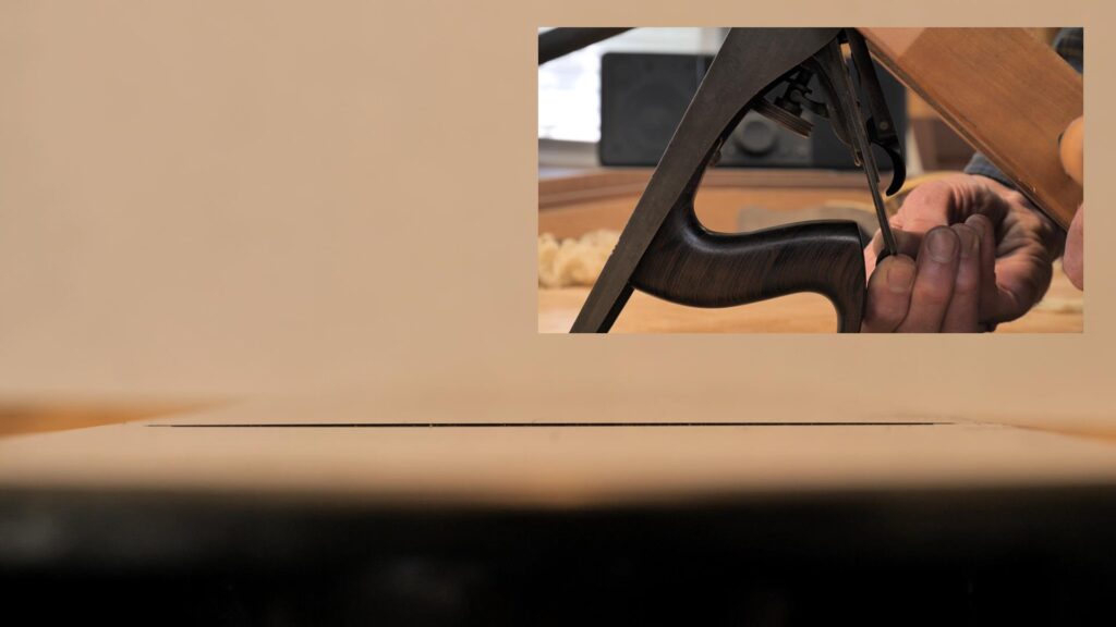
Sighting down the bed, through the mouth, will tell us if the frog is located correctly. If it’s not, the mouth will appear to be tighter on one side than the other. Note that the mouth opening is, technically, the opening between the blade and the front of the mouth, but even without the blade installed, we can see if the opening is parallel. You can see in the next photo that in this case, it is not. The left side is slightly larger than the right side. If we were to install the blade now, with a small mouth opening, shavings might get caught on the right side.

Since the front of the frog is fixed (side-to-side), the orientation of the frog is adjusted from the rear. The forked plate can be moved left or right by loosening its mounting screw and sliding it to the appropriate side. In the photo below, I have moved it to the right (which moves the back of the frog to the left) and you can see the frog is now parallel to the front of the mouth.

Now that the mouth is parallel, we can install the frog attach screws. When tightening the screws, I push back on the frog to ensure it’s tight against the frog adjusting screw. Next, install the blade/chipbreaker assembly and the lever cap. Adjust the depth of cut as desired, adjust the lateral adjuster so the blade edge is parallel to the sole, and now you can (finally!) check the size of the mouth. If it needs adjusting, you’ll have to remove the blade, loosen the frog attach screws, turn the frog adjusting screw in the correct direction, reinstall the blade assembly and lever cap, and check again. It usually takes a couple of tries to get it right.
Note that if your plane does not have the machined slot in the frog and the machined rib on the body, you’ll have to align the frog by eye. It’s not something you have to do often (if ever again), but the machined slot interface is a nice feature to have.
Here’s one of the first shavings and a few shots of the completed plane.